Kompair is an air compressor brand that embodies the excellence of German technology, pioneering in delivering energy-efficient, intelligent, durable, and high-quality compressed air solutionsNot only inheriting Germany’s engineering standards, Kompair also optimizes its manufacturing processes with advanced precision casting technology, delivering outstanding value in terms of performance, durability, and cost-effective investment..
With a focus on sustainable development, Kompair continuously innovates to meet the ever-increasing demands of modern industries, becoming a reliable choice for efficient and long-lasting compressed air systems.

KOMPAIR-
KOMPAIR – German Technology, Smart Compression Solution.
Overview of KOMPAIR Air Compressors
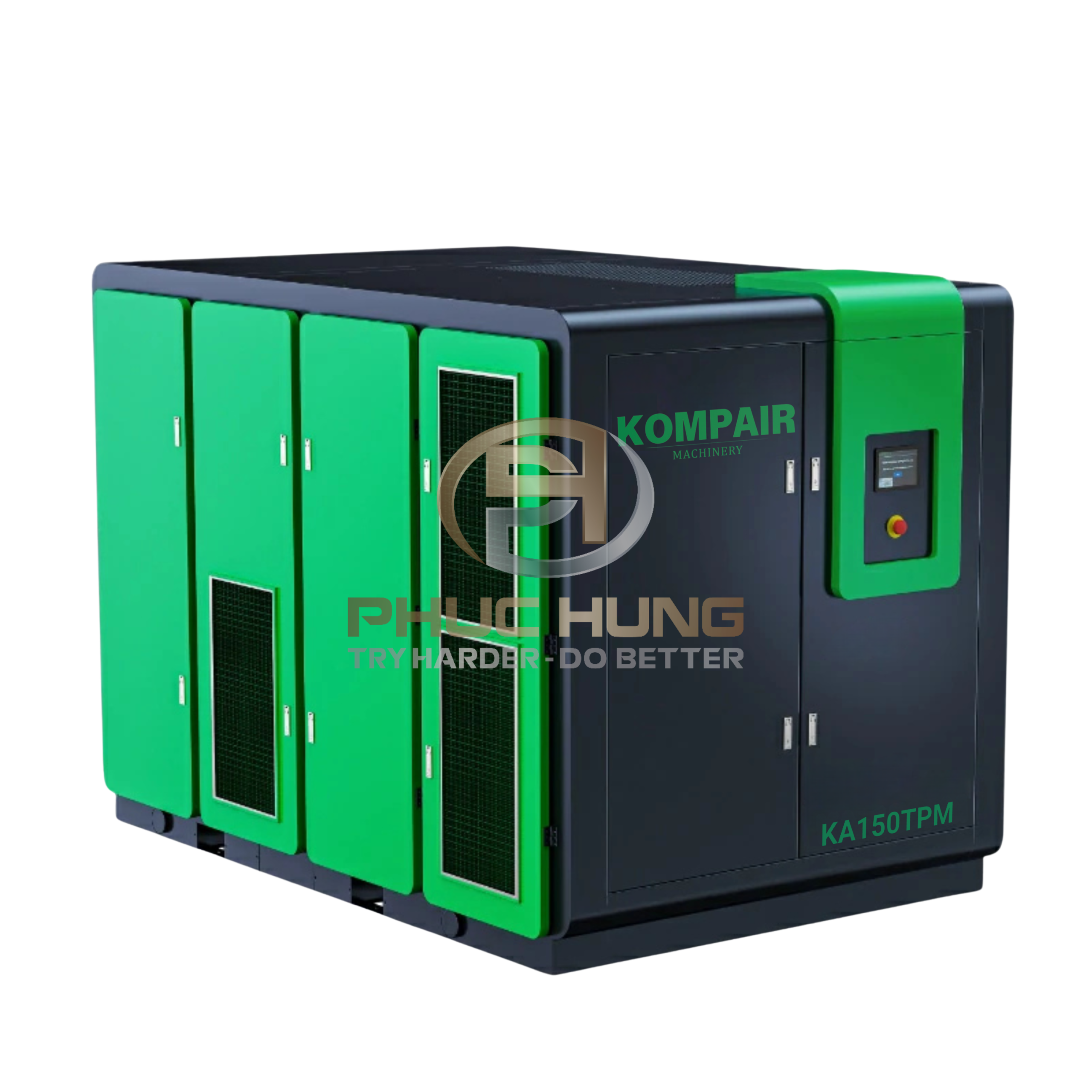
KOMPAIR is a brand focused on high-performance industrial screw air compressors,well known for its two-stage compression two-stage compression technology combined designed to optimize operating costs for factories running under heavy and continuous loads.
The single-stage KOMPAIR has a 2-stage oil-lubricated compressor – Inverter. is designed for:
- Central compressed air system
- The plant is operational 24/7
- Businesses need reduce electricity costs per cubic meter of compressed air.
Two-stage compression technology – The foundation for superior performance.
Unlike single-stage compressors:
- Two-stage compression divides the compression process into two stages.
- Reduces the compression ratio at each stage.
- Reduce the heat generated during the compression process.
Key benefits:
- Significant energy savings
- Higher compression efficiency
- Reduce the load on the compressor and motor.
- Extend equipment service life

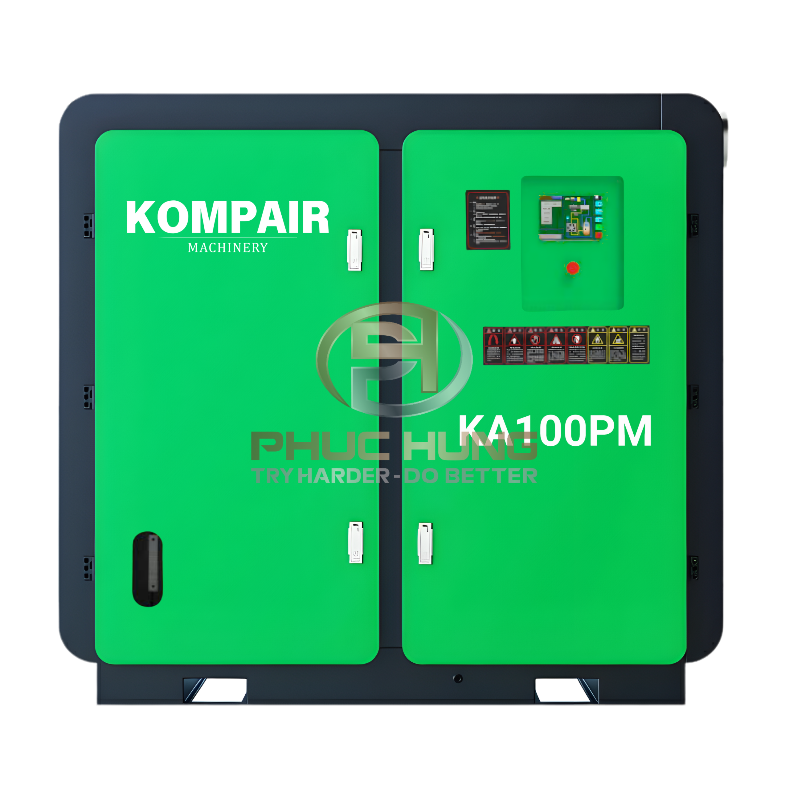
KOMPAIR Oil Injected - Two-Stage - Inverter Air Compressor
Role of oil in KOMPAIR air compressors
KOMPAIR air compressors use oil-injected screw technologyin which the oil performs the following functions:
- Lubricating the screw compressor element
- Seal the compression chamber.
- Reduce friction and wear.
- Supporting compressed air cooling
Thanks to this, the compressor operates operate smoothly, stably, and durably over a long period of time.
Inverter – Optimizing energy according to actual load
The integrated Inverter (VSD) allows:
- Adjusting motor speed according to actual compressed air demand
- Limit idle running.
- Maintaining stable outlet pressure
- Clearly reducing electricity consumption under variable load conditions
This is a key factor that makes KOMPAIR a long-term energy-saving solution.
Principle of operation
- Air is drawn into the first compression stage.
- The intermediate compressed air is cooled.
- Compression continues in the second compression stage.
- The air–oil mixture is separated through a high-performance oil separator
- Clean compressed air is supplied to the system, and the oil is recirculated.
→ Optimized process – high efficiency – stable operation
Typical Specifications – KOMPAIR Oil-lubricated 2-Stage Inverter Air Compressor

Typical specifications – KOMPAIR 2-stage inverter compressor
| Model | Motor output | Maximum pressure | Discharge airflow | Noise level | Air flow outlet size | Coolant | Dimensions | Weight | |
|---|---|---|---|---|---|---|---|---|---|
| L x W x H | |||||||||
| kW | hp | bar | m3/min | dB (A) | inch | L | mm | kg | |
| KA20TPM | 15 | 20 | 7.5 | 0.7~3.0 | 65 | 1 1/2 | 24 | 1550 x 980 x 1300 | 1000 |
| 8.5 | 0.7~2.9 | ||||||||
| 10.5 | 0.6~2.4 | ||||||||
| 12.5 | 0.5~2.0 | ||||||||
| KA25TPM | 18.5 | 25 | 7.5 | 0.9~3.8 | 65 | 1 1/2 | 24 | 1550 x 980 x 1300 | 1100 |
| 8.5 | 0.8~3.4 | ||||||||
| 10.5 | 0.7~2.9 | ||||||||
| 12.5 | 0.7~2.7 | ||||||||
| KA30TPM | 22 | 30 | 7.5 | 1.1~4.5 | 65 | 1 1/2 | 24 | 1550 x 980 x 1300 | 1100 |
| 8.5 | 1.1~4.3 | ||||||||
| 10.5 | 0.8~3.4 | ||||||||
| 12.5 | 0.7~2.9 | ||||||||
| KA40TPM | 30 | 40 | 7.5 | 1.6~6.8 | 68 | 2 | 50 | 1700 x 1130 x 1430 | 1350 |
| 8.5 | 1.5~6.2 | ||||||||
| 10.5 | 1.2~4.7 | 1 1/2 | 24 | 1550 x 980 x 1300 | 1150 | ||||
| 12.5 | 1.1~4.3 | ||||||||
| KA50TPM | 37 | 50 | 7.5 | 1.9~7.5 | 68 | 2 | 50 | 1700 x 1130 x 1430 | 1450 |
| 8.5 | 1.8~7.4 | ||||||||
| 10.5 | 1.5~6.0 | ||||||||
| 12.5 | 1.4~5.6 | ||||||||
| KA60TPM | 45 | 60 | 7.5 | 2.3~10.0 | 68 | 2 | 50 | 1700 x 1130 x 1460 | 1700 |
| 8.5 | 2.2~8.6 | ||||||||
| 10.5 | 1.9~7.5 | ||||||||
| 12.5 | 1.6~6.4 | ||||||||
| KA75TPM (W) | 55 | 75 | 7.5 | 3.0~13.1 | 70 | 2 1/2 | 70 | 2250 x 1370 x 1700 (2300 x 1500 x 1750) | 2200 (2200) |
| 8.5 | 2.8~12.3 | ||||||||
| 10.5 | 2.3~10.1 | 2 | 50 | 1850 x 1180 x 1430 (1800 x 1320 x 1370) | 2000 (2000) |
||||
| 12.5 | 2.3~9.0 | ||||||||
| KA100TPM (W) | 75 | 100 | 7.5 | 4.2~16.6 | 70 | DN65 | 70 | 2300 x 1670 x 1690 (2300 x 1500 x 1750) | 2400 (2400) |
| 8.5 | 3.8~15.6 | ||||||||
| 10.5 | 3.4~13.6 | 2 1/2 | 2250 x 1370 x 1700 (2300 x 1500 x 1750) | 2300 (2400) |
|||||
| 12.5 | 2.9~11.5 | ||||||||
| KA120TPM (W) | 90 | 120 | 7.5 | 5.3~20.8 | 73 | DN80 | 100 | 2750 x 1780 x 1950 (2750 x 1780 x 1950) | 3300 (3700) |
| 8.5 | 4.9~20.0 | ||||||||
| 10.5 | 4.1~16.3 | DN65 | 70 | 2300 x 1670 x 1690 (2300 x 1500 x 1750) | 2600 (3200) |
||||
| 12.5 | 3.9~15.3 | ||||||||
| KA150TPM (W) | 110 | 150 | 7.5 | 6.1~24.5 | 73 | DN80 | 100 | 2750 x 1780 x 1950 (2750 x 1780 x 1950) | 3800 (3400) |
| 8.5 | 5.8~23.5 | ||||||||
| 10.5 | 5.1~20.1 | ||||||||
| 12.5 | 4.4~17.3 | ||||||||

Typical specifications – KOMPAIR 2-stage inverter compressor
| Model | Motor output | Maximum pressure | Discharge airflow | Noise level | Air flow outlet size | Coolant | Dimensions | Weight | |
|---|---|---|---|---|---|---|---|---|---|
| L x W x H | |||||||||
| kW | hp | bar | m3/min | dB (A) | inch | L | mm | kg | |
| KA160TPM (W) | 120 | 160 | 7.5 | 6.5~26.0 | 73 | DN100 | 120 | 2900 x 1940 x 1950 (2900 x 1940 x 1950) | 4200 (3900) |
| 8.5 | 6.1~24.8 | ||||||||
| 10.5 | 5.6~22.9 | DN80 | 100 | 2750 x 1780 x 1950 (2750 x 1780 x 1950) | 4000 (3600) |
||||
| 12.5 | 4.7~19.2 | ||||||||
| KA175TPM (W) | 132 | 175 | 7.5 | 7.2~30.0 | 73 | DN100 | 120 | 2900 x 1940 x 1950 (2900 x 1940 x 1950) | 4300 (4000) |
| 8.5 | 6.9~28.0 | ||||||||
| 10.5 | 6.1~24.1 | ||||||||
| 12.5 | 5.4~21.3 | ||||||||
| KA200TPM (W) | 150 | 200 | 7.5 | 8.1~33.0 | 78 | DN125 | 150 | 3250 x 1950 x 2150 (3250 x 1950 x 2150) | 5000 (5500) |
| 8.5 | 7.4~30.0 | ||||||||
| 10.5 | 6.5~28.0 | DN100 | 120 | 2900 x 1940 x 1950 (2900 x 1940 x 1950) | 4100 (4300) |
||||
| 12.5 | 6.1~24.3 | ||||||||
| KA215TPM (W) | 160 | 215 | 7.5 | 8.8~35.0 | 78 | DN125 | 150 | 3250 x 1950 x 2150 (3250 x 1950 x 2150) | 5000 (5000) |
| 8.5 | 8.1~33.0 | ||||||||
| 10.5 | 7.7~30.0 | DN100 | 120 | 2900 x 1940 x 1950 (2900 x 1940 x 1950) | 4500 (4100) |
||||
| 12.5 | 6.5~26.3 | ||||||||
| KA250TPM (W) | 185 | 250 | 7.5 | 10.7~42.0 | 78 | DN125 | 150 | 3250 x 1950 x 2150 (3250 x 1950 x 2150) | 5400 (6200) |
| 8.5 | 10.3~40.0 | ||||||||
| 10.5 | 8.8~35.5 | ||||||||
| 12.5 | 7.5~32.4 | ||||||||
| KA270TPM (W) | 200 | 270 | 7.5 | 11.0~44.0 | 80 | DN125 | 180 | 3500 x 2250 x 2300 (3500 x 2100 x 2400) | 6200 (6000) |
| 8.5 | 10.5~42.0 | ||||||||
| 10.5 | 9.7~38.6 | ||||||||
| 12.5 | 8.2~33.0 | ||||||||
| KA300TPM (W) | 220 | 300 | 7.5 | 12.4~49.6 | 80 | DN125 | 180 | 3500 x 2250 x 2300 | 6400 (6200) |
| 8.5 | 11.5~46.0 | ||||||||
| 10.5 | 10.3~41.2 | ||||||||
| 12.5 | 9.5~38.1 | ||||||||
| KA340TPM (W) | 250 | 340 | 7.5 | 13.8~55.3 | 82 | DN150 | 200 | 3800 x 2300 x 2400 (3800 x 2300 x 2400) | 8000 (7300) |
| 8.5 | 13.3~51.0 | ||||||||
| 10.5 | 11.7~46.0 | DN125 | 180 | 3500 x 2250 x 2300 (3500 x 2100 x 2400) | 6600 (6400) |
||||
| 12.5 | 10.3~41.2 | ||||||||
| KA375TPM (W) | 280 | 375 | 7.5 | 15.1~60.5 | 82 | DN150 | 200 | 3800 x 2300 x 2400 (3800 x 2300 x 2400) | 8100 (7800) |
| 8.5 | 14.1~56.5 | ||||||||
| 10.5 | 12.8~51.0 | ||||||||
| 12.5 | 11.6~46.0 | ||||||||
| KA400TPM (W) | 300 | 400 | 7.5 | 16.2~65.0 | 85 | DN150 | 200 | 3800 x 2300 x 2400 | 8300 |
| 8.5 | 15.0~60.3 | ||||||||
| 10.5 | 14.1~56.5 | ||||||||
| 12.5 | 12.8~51.5 | ||||||||
| KA440TPM (W) | 330 | 440 | 7.5 | 17.7~70.7 | 85 | DN150 | 200 | 3800 x 2300 x 2400 | 8600 |
| 8.5 | 16.2~65.0 | ||||||||
| 10.5 | 15.0~60.2 | ||||||||
| 12.5 | 14.1~56.5 | ||||||||
Core technology that enables intelligent and energy-efficient compressor operation
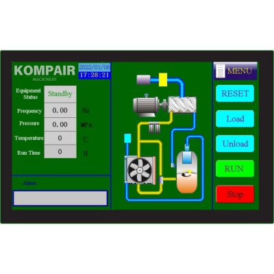
Smart controller
The system is equipped with a multi-language PLC controller featuring an intuitive and user-friendly interface, allowing operators to monitor and adjust the compressor quickly and safely.
Integration 14 protection functions such as overload protection, short circuit protection, reverse polarity protection, overvoltage protection, and high/low temperature protection, ensuring comprehensive safety for all internal components.
The intelligent drive control system automatically adjusts motor speed according to actual air demand,supports load start and soft start, and helps optimize overall operating efficiency. The display screen provides real-time operating information, including pressure, temperature, and operational performance charts.
A large memory capacity enables remote monitoring via computer and supports the connection and with coordinated control of multiple compressors,maximizing the efficiency of the entire compressed air system.
Smart controller
New generation ultra-stable inverter
When it comes to energy-saving solutions for air compressors, inverter technology is always a key factor. In the past, equipping an air compressor with a variable frequency drive (VFD) typically increased the initial investment cost by approximately 20–30% of the equipment value.
Recognizing the growing demand for energy efficiency and cost optimization among businesses—especially in modern manufacturing models —Kompair’s Inverter solution has been developed with proprietary technology. This solution delivers ultra-stable operation, high performance,and a significantly more optimized initial investment compared to conventional inverter systems.
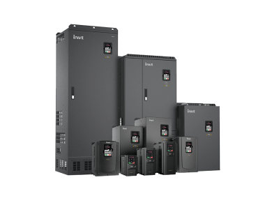
New generation ultra-stable inverter
Two-Stage Compression Airend – Optimized Isothermal Compression Technology


Isothermal compression technology:
After the first compression stage, coolant is atomized and injected through multiple ports on the compressor housing, effectively cooling the hot compressed air. As a result, the air temperature before entering the second compression stage is significantly reduced, bringing the compression process closer to an isothermal state—the most energy-efficient compression method available today.
Two-Stage Compression:
The two-stage compression system establishes a balanced pressure ratio between the compression stages, reducing the compression ratio at each stage compared to single-stage compression. This design helps to:
- Minimize air leakage between the rotors
- Improve volumetric efficiency and thermal efficiency
- Increase the compressed air output flow
- Reduce the load on the airend, thereby enhancing equipment durability and service life
As a result, two-stage air compressors can achieve energy savings of approximately 15–30%, with while offering a service life of up to twice as long compared to single-stage compressors with the same capacity.